Lighthouse Controller
Kit Construction
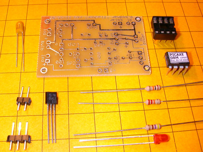
The first step in constructing the lighthouse controller kit uses the parts in this photo. The parts include:
circuit board
filter capacitor
2 pin and 3 pin headers
78L05 voltage regulator
10K resistor
22K resistor
470 resistor
8 pin IC socket
Picaxe processor
red LED
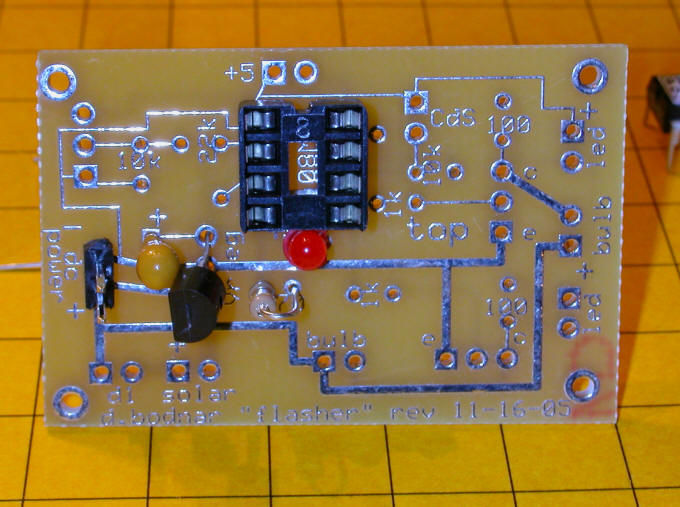
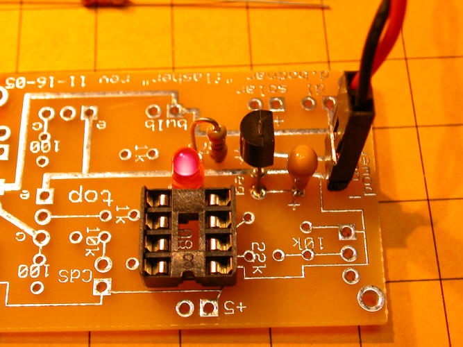
Place and solder the IC socket. Note that the notch in the socket is at the top
Insert and solder the 2 pin header in the pins labeled "dc power"
Insert and solder the filter capacitor - note that the "+" on the board must match up with the "+" on the capacitor.
Insert and solder the 3 pin 7805 voltage regulator. Note that its flat face goes to the left, as in the photo.
Insert and solder the 470 ohm (yellow/violet/brown) resistor
Insert and solder the red LED. Its longer lead goes into the "+" hole.
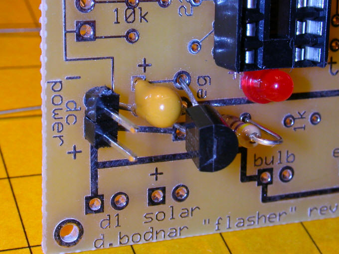
This close-up may help with parts placement. Note that the labeled side of the capacitor is not visible, as it faces the 78L05.
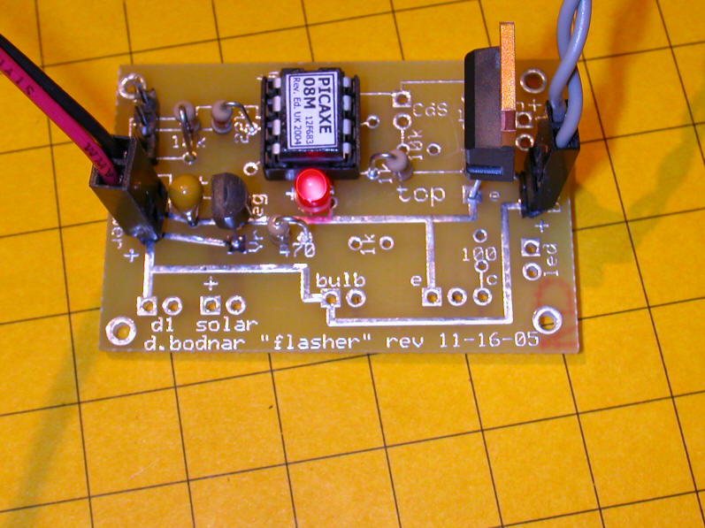
After soldering clip all leads off close to the board as in this photo. Check for solder bridges and bad joints.

Once you are SURE everything is in order plug the power supply onto the "dc power" pins. MAKE SURE YOU OBSERVE PROPER POLARITY or you will destroy the voltage regulator. The red (positive) wire MUST go to the post marked "+".
The LED should light brightly. If it does DISCONNECT IMMEDIATELY and check for bad solder joints, reversed components or solder bridges.
Once the LED lights properly proceed with the next step. Note that this step can be skipped if you don't plan on programming the Picaxe.
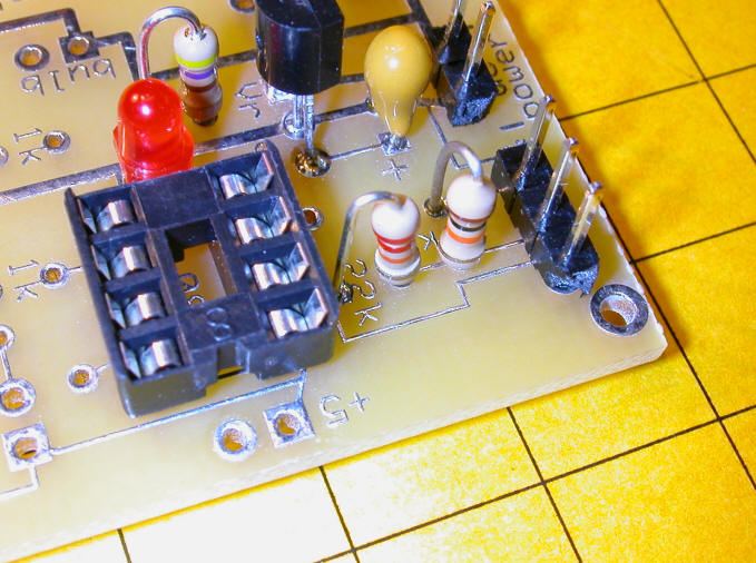
Insert the 3 pin header, 22K resistor (red/red/orange) and 10K resistor (brown/black/orange) as in the photo. Solder and clip leads.
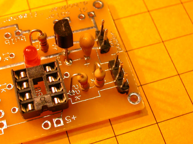
Close-up
The parts for the last step are below.
1K resistor
2 pin header
TIP120 transistor
12volt halogen bulb with cable attached
Note that the leads of the TIP120 have been bent to facilitate placement on the board. The black tubing keeps the base and collector leads from shorting. Make sure they don't touch!

Insert and solder the 1K resistor (brown/black/brown) and TIP120 - be sure to place the TIP120 as shown.

Insert the Picaxe chip into its socket. Make sure the label is as shown. You will also note a small indentation on the left side of the chip. This denotes the end with pin 1 and must be to the left as shown above. Be careful to insert the pins directly into the socket. You may need to bend them in a bit to get them to fit properly. If you are not sure if they went in properly gently pry the chip out with a small screwdriver and try again.
Plug the halogen bulb into the header near the TIP120 and plug
the power supply back in. You should be rewarded with a flashing
lighthouse!