|
.JPG) |
|
Sensor Options
-
The sensors for the MTSC are made up of a pair of infrared LEDs and a pair of
infrared detectors. As mentioned earlier, the IR LEDs are pulsed at a
frequency of 38 KHz and the detectors only respond to IR at that frequency.
-
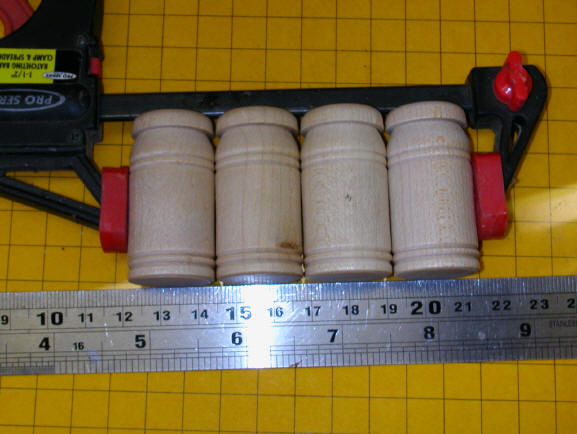
The MTSC comes with one set of sensors that are mounted
in a clear, plastic "U" shaped bracket. This mounting method allows
users to place the sensors over the track so that they can easily be moved
from place to place on the layout or to another layout entirely. This is
shown in the photo at the top of this page.
-
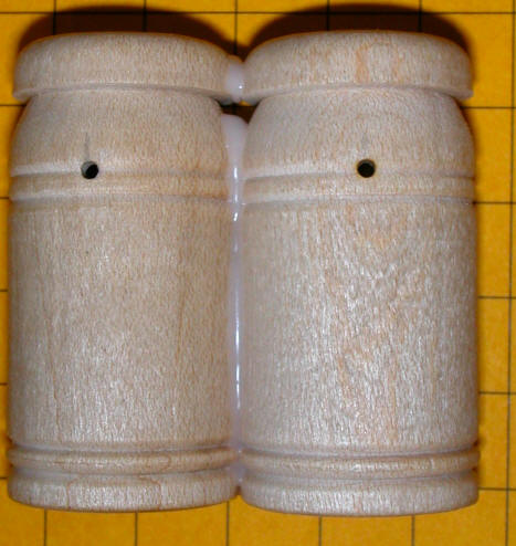
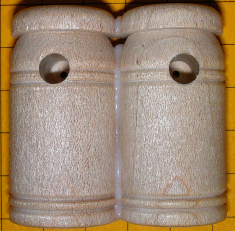
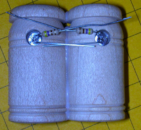
The
sensors can be mounted in any number of trackside scenery items. The
photos below show two "G" scale installations, one inside of two wooden
barrels and the other inside of piles of railroad ties.

.JPG)
|
|
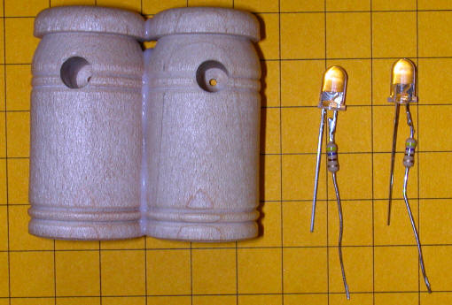
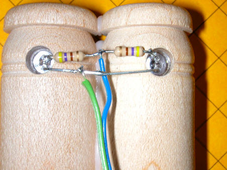
This photo shows the indicator LEDs that light red when the
IR emitters and detectors are properly aligned.
.JPG)
|
|
Mount Your Own Sensors
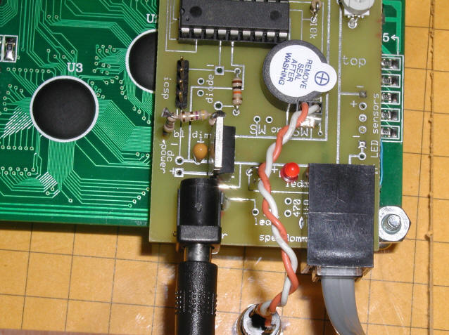
A package consisting of two IR LEDs, two red
indicator LEDs, 4 current limiting resistors, two 38 KHz IR detectors, one
filter capacitor and a connecting cable that is terminated in an RJ-12 plug that
fits into the Speedometer board is available for those of you who would like to
mount your own sensors in a building, or other track-side piece of scenery
|
|
To mount your own follow these steps:
|
|
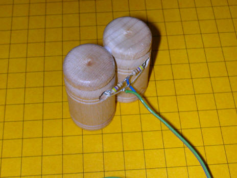
IR EMITTER CONSTRUCTION
.
-
To mount the LEDs drill two 1/16" holes in
your object, 1" apart. These holes will allow the LED "light" to exit.
If you have difficulty drilling small holes you can drill larger holes and place
small pieces of brass tubing with a 1/16" inside diameter in them. The
important thing is that the amount of IR that is permitted to escape is limited
to what can pass through a hole no larger than 1/16".
-
Wiring is very simple. The remaining
ends of the two resistors are connected together and the two negative leads of
the LEDs are also connected together. If you have difficulty identifying
the leads, the longer one is positive and the negative one is next to the flat
spot on the side of the LED's base. You must take care that the two leads
of the LEDs don't touch and short out. Bending them as in the photo helps
to keep this from happening.
|
|
Custom Sensors
Custom sensor mounting is available. Due
to the time involved in making and testing custom sensors the price is based on
time and materials. The price for the sensors, wiring and other parts is
in the price list. Most custom sensor installation takes between 1 and 2
hours which is billed at $30.00 per hour.
|
| |
| |
| |
| |